applying to several dozen internships only to get a fat goose egg leads engineering majors to say the same thing: "i'll do personal projects". perhaps it will look good on a resume, though it will probably vanish after about a year in corporate. unemployment haunts engineering majors, especially in a university crawling with bay area kids born with a linux-installed thinkpad right out of the womb. envy grows when ee majors realize their classmates have parents in tech and therefore they not only have all the resources, but also only need to put in a fraction of the effort others do to so called "succeed" in the tech industry.
my project of choice was cloning guitar pedals, and the reason is because i can
the circuit i chose to clone was an ibanez tube screamer. this circuit is a terrifyingly oft-cloned circuit, with oodles of boutique pedals essentially copying the structure of this pedal while adding trivial features e.g. eq controls to justify a $70 increase to the price. the best tube screamer clone i've seen is the horizon devices precision drive, which incorporates a crispy knob which broadens the mod i made to my clone. the circuit guide to the tube screamer is found here.
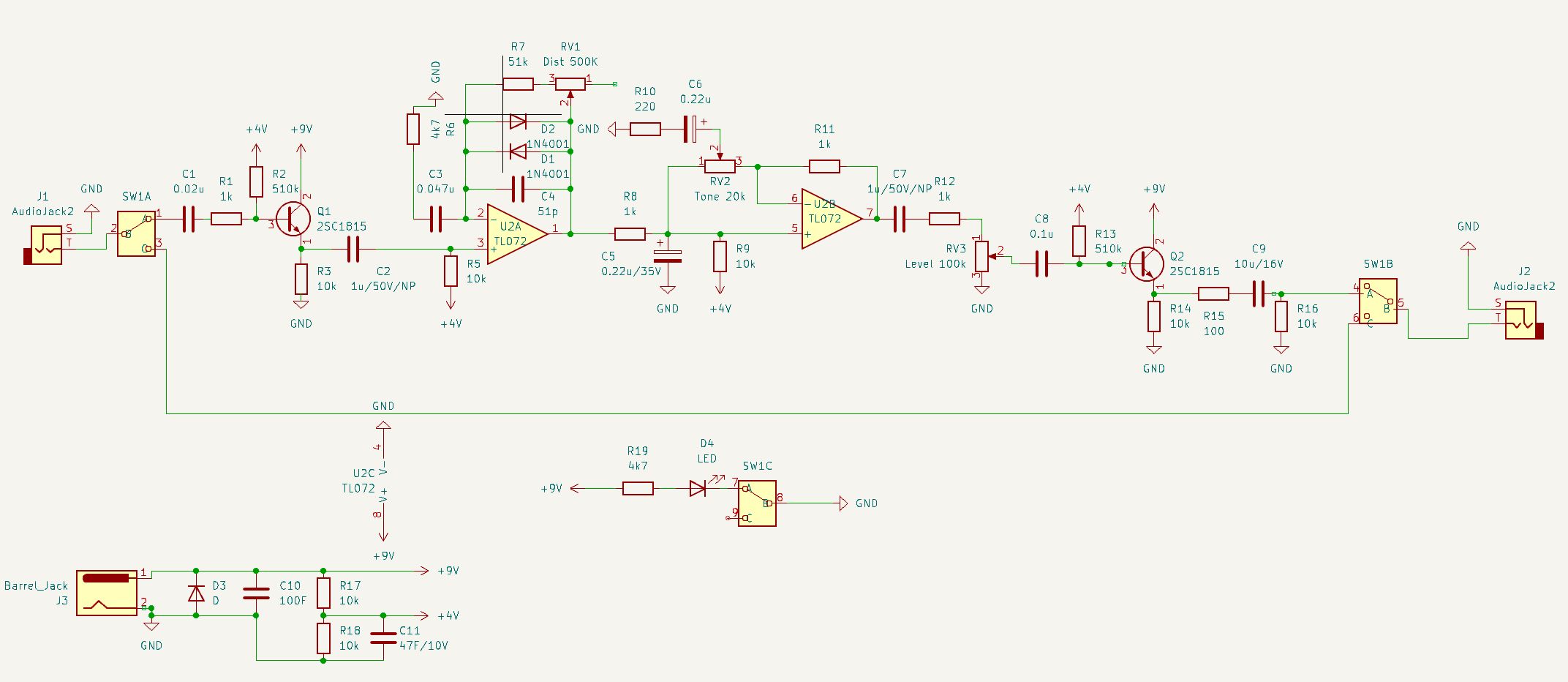
the circuit consists of the following sections
its just a 9V input from a jack that is split in half by two resistors and smoothed out with a capacitor. a diode is added just to prevent funny backflow. nothing too special here
the input stage is a pretty standard common collector/emitter follower bjt amplifier. a capacitor ac couples the oscillation to make biasing more precise (as a disclaimer, this is done a lot in this circuit). there is a 4.5V input bias to make sure the input is running circles around the dead center of the voltage supplied to the transistor, which is 9 volts therefore it does its magic to voltages between 0 and 9 volts. apparently the buffer creates high input impedance, something that is seemingly sought after and ideal for audio signals but then again i'm two classes away from knowing why
this is where the funny stuff is. after another round of ac-coupling/biasing, the signal goes through an op amp, which is in a feedback loop with two diodes, a potentiometer, and a capacitor. my friend pepper pointed out that the capacitor is used to prevent self oscillation, but i am curious about what is would sound like with the self oscillation. the diodes point in opposite ways, which causes the signal to clip. however, notice that the diodes are in a feedback mechanism, therefore it does not simply slice the voltage off at a value but rather makes the voltage approach that value so to speak. the potentiometer therefore dictates how fast it reaches that value, or more accurately it changes the gain so it will get louder faster as it hits the clipping point.
there is a high pass filter in the feedback path, and this is where my mod comes in. the capacitive high pass filter follows the standard formula of f = 1/2πRC, and the capacitor value used in the capacitor used is a 0.047 uf cap which allows frequencies over 720 hz to fully clip. i increased the capacitance to around 0.22 uf, which should lower that threshold to 154 hz. this means more overdrive for more more frequencies, giving guitars a raunchier, dirtier sound and giving basses a rich, deep distortion that would sound otherwise thin without the mod
this is simply an active low pass filter used to cut out the shrill high frequencies introduced into by the distortion. nothing too special
basically the same thing as the input stage with the purpose of strengthening the signal as it enters another barrage of pedals by creating low output impedance. imagine the first part of the circuit all over again. There is an annoying 10 uf ceramic capacitor that was difficult to source therefore i had to go to taiwan to buy the caps. the problem is solved now that i got a box filled with millions of capacitors
did i mention this pedal is true bypass?! truth be told, i did not want to bother with the difficulty of making the jfet switching found in the original pedal, and since i already had to order footswitches i might as well just order the 3pdt ones that make my life significantly easier.
the schematic is essentially identical with the one on the website and looks as follows:
the capacitor mod was done separately after testing it out with the original circuit.
footprints were probably one of the most tedious parts of making the pcb. of course, routing the pcb itself took finesse, but it wasn't as mundane as measuring resistors and capacitor sizes, making a footprint for the switch, downsizing the pot footprints, etc. i ended up utilizing my golden gate bridge tourist trap multitool pen which has a ruler and started measuring everything. in the end, every part more or less fit. all traces were 0.4 mm.
placing components took multiple rounds of trial and error. my goal was to minimize my usage of the back layer to reserve it for power and ground, but i ended up filling both sides with ground and letting all the traces slither across their most efficient path. the two inputs had to be jumper-ed to the switch because creating a trace would be very long and take up real estate that i do not want to squander on two lossy paths (is that the right way to use the word?). below is the pcb, and reserve your judgement as this is my first ever pcb and you will see improvements if you just wait.
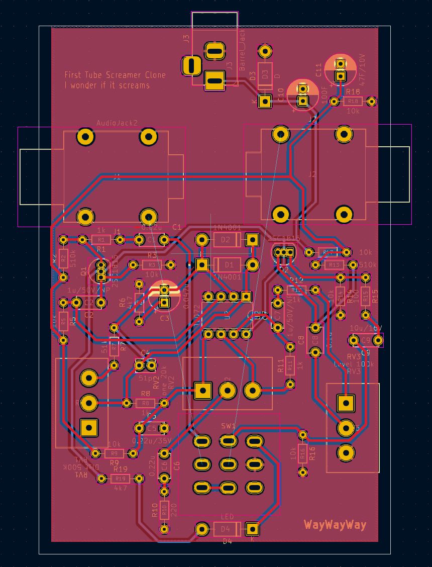
as evident, there is an ignorant amount of wasted space, poor placement, and even poorer footprint creation for the pots and audio jacks. alas, this was the one i printed out and implemented to surprising success. the issues to this pcb include the following
the end result of this current iteration looks like this:
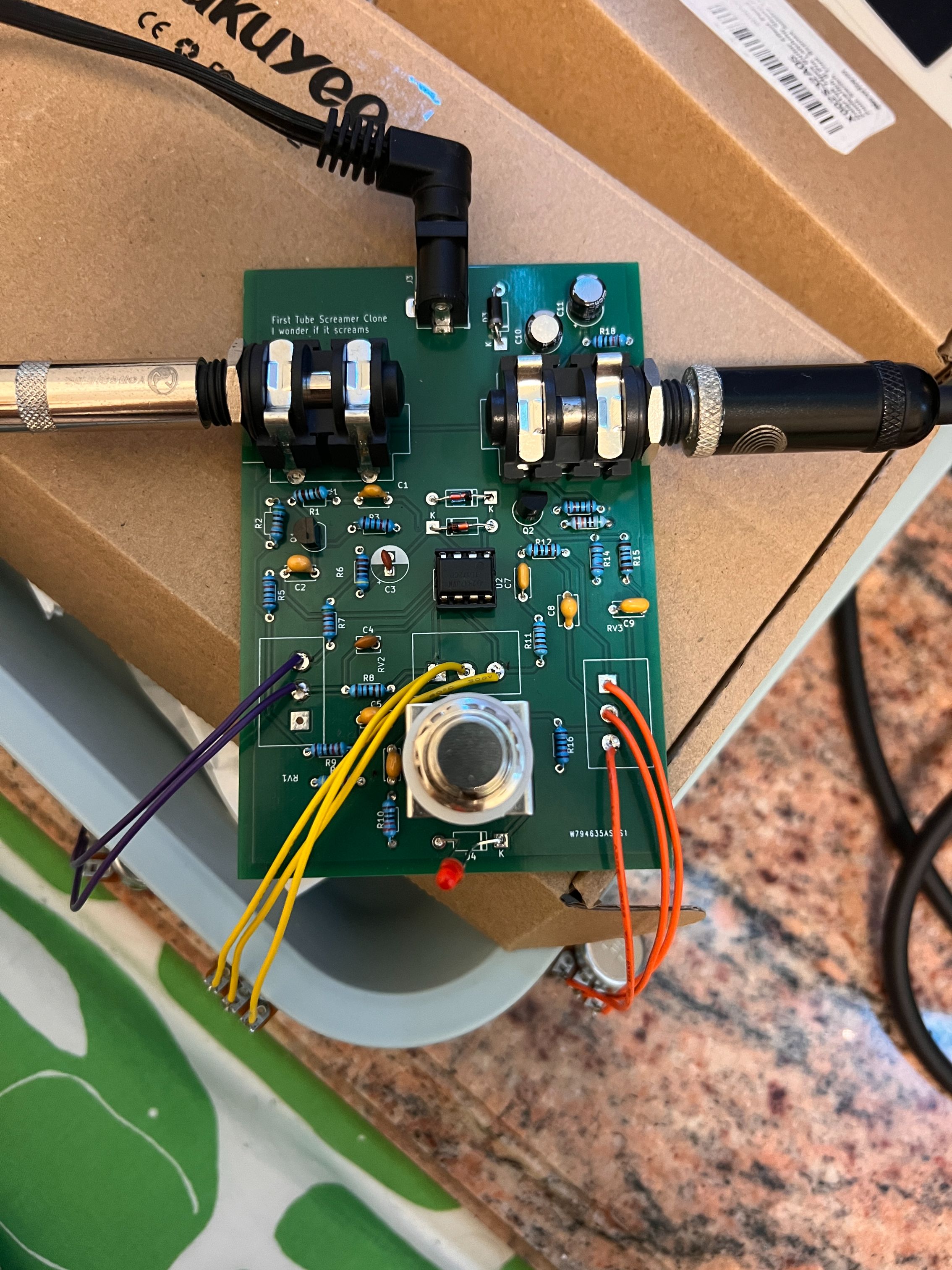
after returning to los angeles, i consulted my good friend alexiy for guidance regarding creating pedals. i told him that all the capacitors i used were ceramic capacitors, and apparently due to the low equivalent series resistance and microphonic nature of ceramic capacitors the tone it produces is quite abundant on the high end, causing my pedal to sound shrill. using film capacitors should have been the move, however they were quite expensive at the place i source components so i just skipped over them. well, maybe next time.